3D Printed OpenSCAD Word Glasses
Generating and printing customisable glasses with OpenSCAD
This post describes the process of designing my Customisable Word Glasses (click here to customise your own pair) using OpenSCAD. It’s not intended as a full tutorial, but hopefully emphasises the important parts of the OpenSCAD script I wrote. Some code samples are given through the post and the full script is given at the bottom.
A couple of years ago I bought a 3D printer. I’d wanted one more-or-less since the day I learnt they actually existed, but for years they were firmly out of my price range. In 2012 RepRapPro started offering a RepRap Huxley kit at a relatively low price. I was sold! The printer arrived as a large box filled with nuts, bolts, threaded bar, a number of 3D printed components and a lot of electronics. It took me close to a month of evenings to assemble and calibrate. Eventually (after a lot of tweaking) it was working and I was ready to print something!
Around this time the MakerBot Customiser Challenge caught my eye. The customiser is a web wrapped for the OpenSCAD solid model programming language, allowing users of Thingiverse to easily customise 3D models. The competition was to design something with OpenSCAD which was useful, wearable or artistic. The prize in each category was a MakerBot Replicator 2. It seemed like a good prize and a good opportunity to learn something new.
My concept was a pair of glasses which spelled out a word over the wearer’s eyes. My entry was selected as a runner up in the competition.
The Design
The entire design was done in OpenSCAD. I found this quite different from working in Solidworks or other parametric 3D CAD. OpenSCAD works through additive or subtractive 3D modelling, and so each step of the design progression requires quite a lot of visualisation in your mind. The design process tends to involve placing a shape, deciding that the position or scale should change, trying to understand how that shape’s coordinate system is aligned, changing a dimension and discovering that it’s moved the wrong way. Rinse and repeat. Needless to say it can be quite a slow process.
The Frame
I created the glasses frame by joining a number of circles and semi-circles together with a “hull” join. To make quarter-turn semi-circles, I needed to define my own module:
//creates a quarter circle centered at 0,0 and in the positive quadrant
module quarter_arc(radius) {
    intersection() {
    square([radius,radius]);
    circle(r = radius, $fn=50); //bottom left
    }
}
Then I defined the shape of the glasses:
//creates the shape of the eye
module eye_shape(size) {
    //join lots of circles and quarter_circles together
    hull() {
        //top left
        translate([size*15, 0, 0]) circle(r = size*15, $fn=50);
        //rounded top
        //translate([size*33, size*-30, 0]) rotate(a=[0,0,45]) quarter_arc(size*47);
        //top right
        translate([size*53, 0, 0]) circle(r = size*15, $fn=50);
        //bottom left
        translate([size*23, size*-9.5, 0]) rotate(a=[0,0,180]) quarter_arc(size*23);
        //rounded bottom
        //translate([size*30, size*-8, 0]) rotate(a=[0,0,240]) quarter_arc(size*25);
        // bottom right
        translate([size*43, size*-9.5, 0]) rotate(a=[0,0,270]) quarter_arc(size*23);
    }
}
You’ll notice that this module actual has an argument - “size”. This is because to make a glasses frame you need to later subtract a slightly scaled-down version of the same shape. It’s a lot easier if you have one module that generates it!
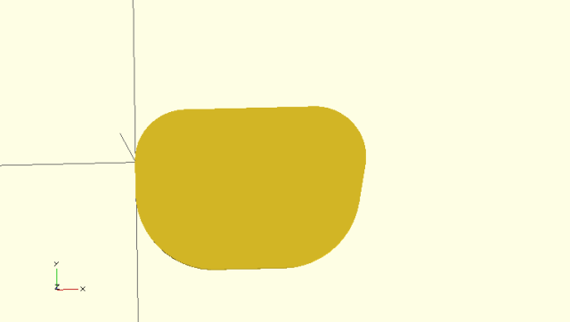
Now we can extrude just this shape:
linear_extrude(height=3) {
    eye_shape(1);
}
And this is what we get
We need more than just the shape of the lense though. Real glasses need a bridge, a hinge for the arm and a hole to see out of! We can run the last command again, but this time make use of the “difference” command to give us a frame with a hole. The “union” command combines the bridge and hinge with the main lense into a single 3D object.
linear_extrude(height=3) {
    difference() {
        // a big eye shape is made, and squares for the bridge and hinge join added
        union() {
            eye_shape(1);
            //bridge
            translate([50, -1, 0]) square([25, 15.5]);
            //hinge
            translate([-5, -8, 0]) square([9, 10]);
        }
        // we subtract a slightly scaled eye shape. Offset needs to be calculated if scale (or glasses dimensions) change.
        translate([4.5,-1 ,0]) eye_shape(0.88);
    }
}
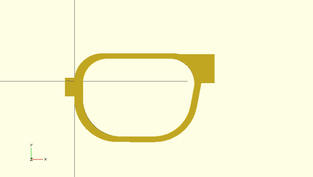
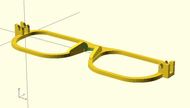
That doesn’t look very comfortable though! In my final code I subtracted semi-circles from the top and bottom of the bridge piece to give a more curved finish. I then created a “nose piece” using a hull of 3 more semi-circles. To create a full glasses frame I created a mirrored version of my half frame and lined it up with the original. The full code for the glasses (including the frame and the hinge) is further down.
The Hinge
Designing a functioning hinge proved rather difficult. My first design was a snap-together one, utilising two long tabs with small bumps on the end. A single tab with circular indentations on either side was mounted on the arm, and so it could slot inbetween the tabs and lock. This was inspired by similar designs used on other 3D printed glasses.
Getting the dimensions correct proved tricky, so I ended up printing a number of small parts which just allowed me to test different configurations of hinge.
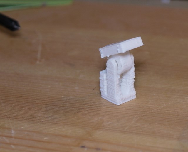
Ultimately although my tests seemed solid enough, the design was a failure. With a longer lever arm on each side of the hinge, the long tabs snapped off with little effort. It transpired that the orientation that they were printed meant that each tab was made up of hundreds of layers of plastic, with the join between each layer very susceptible to fracturing.
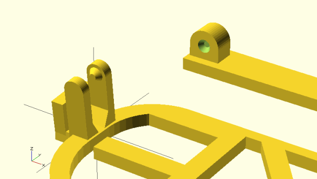
Some glasses models intended for 3D printing available online use a “hinge pin” to join the arm and glasses frame together. These designs all used a 3D printed pin. Unfortunately my poorly calibrated printer wasn’t capable of the tolerances required. Fortunately I had a ready source of small cylindrical plastic - 3D printer filament.
The final hinge design has holes on both the arm and frame. The holes can be lined up and a small piece of 1.75mm or 3mm PLA or ABS filament can be slid through. Because overhangs are very tricky in additive 3D printing, a slice had to be cut out of the top of the hinge.
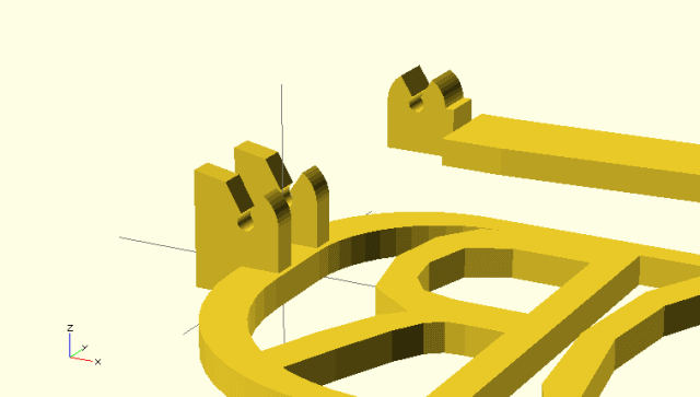
And so my final frame:
Adding Text
I used the Write module for OpenSCAD to write the letters. The letters were written individually to allow each to be translated separately.
//defines the letters
module words(l_ltr1, l_ltr2, r_ltr1, r_ltr2, l_trns1, l_trns2, r_trns1, r_trns2) {
    union() {
        translate([155,1.5,0]) mirror([1,0,0]) {
            translate([l_trns1,-32,0]) scale([0.82,1,1]) write(l_ltr1,t=3,h=43);
            translate([l_trns2,-32,0]) scale([0.82,1,1]) write(l_ltr2,t=3,h=43);
            translate([r_trns1,-32,0]) scale([0.82,1,1]) write(r_ltr1,t=3,h=43);
            translate([r_trns2,-32,0]) scale([0.82,1,1]) write(r_ltr2,t=3,h=43);
        }
    }
}
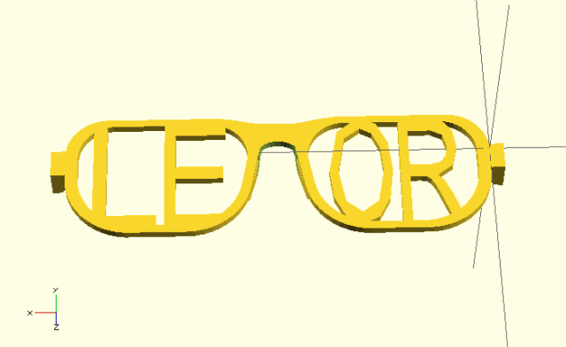
The intersection command was used with the lens shape defined earlier. This meant that only the parts of the letters which fitted within the glasses frame were extruded.
intersection() {
    translate([0,0,-1]) linear_extrude(height=5) {
    union() {
            eye_shape(0.97);
	translate([150,0,0]) mirror([1, 0, 0])	eye_shape(0.97);
        }
     }
     words(word[0],word[1],word[2], word[3],15+s1,40+s2,98+s3,123+s4);
}
OpenSCAD Source Code
Some modifications were made to this to allow compatibility with the Thingiverse Customiser application, allow better text placement in 1, 2 or 3 character cases and to add arms into the final model for easier printing. You can customise your own pair on Thingiverse by clicking here.
use <write/Write.scad>

//The word to write (1 to 4 characters)
word="LEOR";

// Which one would you like to see?
part = "frame"; // [both:Arms and frame,frame:Only the frame,arms:Only the arms]

// Shift letter 1 by?
letter_1_shift = 0;

// Shift letter 2 by?
letter_2_shift = 0;

// Shift letter 3 by?
letter_3_shift = 0;

// Shift letter 4 by?
letter_4_shift = 0;

//Hinge filament diameter?
hinge_diameter = 1.77;

// preview[view:south, tilt:bottom diagonal]

print_part();

wordlength = len(word);

module print_part() {
	if (part == "frame") {
		only_frame();
	} else if (part == "arms") {
		only_arms();
	} else if (part == "both") {
		build_print();
	} else {
		build_print();
	}
}


module only_arms() {
	//place the two arms
	translate([0,4,0]) arm();
	translate([0,-4,0]) mirror([0,1,0]) arm();
}

module only_frame() {
	union() {
		//place the glasses frame
		place_frame();
		//place the words
		place_words();
	}
}

module build_print() {
	only_frame();
	//place the two arms
	translate([0,35,0]) arm();
	translate([0,-50,0]) mirror([0,1,0]) arm();
}

//creates a quarter circle centered at 0,0 and in the positive quadrant
module quarter_arc(radius) {
intersection() {
	square([radius,radius]);
	circle(r = radius, $fn=50); //bottom left
}
}

//creates the shape of the eye
module eye_shape(size) {
	//join lots of circles and quarter_circles together
	hull() {
		//top left
		translate([size*15, 0, 0]) circle(r = size*15, $fn=50);
		//rounded top
		//translate([size*33, size*-30, 0]) rotate(a=[0,0,45]) quarter_arc(size*47);
		//top right
		translate([size*53, 0, 0]) circle(r = size*15, $fn=50);
		//bottom left
		translate([size*23, size*-9.5, 0]) rotate(a=[0,0,180]) quarter_arc(size*23);
		//rounded bottom
		//translate([size*30, size*-8, 0]) rotate(a=[0,0,240]) quarter_arc(size*25);
		// bottom right
		translate([size*43, size*-9.5, 0]) rotate(a=[0,0,270]) quarter_arc(size*23);
	}
}

//defines the nose piece
module nose_piece() {
	//width of 3
	linear_extrude(height=3) {
		//it's a hull of 3 arcs
		hull() {
		quarter_arc(6, $fn=50);
		rotate([0,0,300]) quarter_arc(6, $fn=50);
		translate([0, -12, 0]) rotate([0,0,270]) quarter_arc(3, $fn=50);
		}
	}
}

//defines the letters
module words(l_ltr1, l_ltr2, r_ltr1, r_ltr2, l_trns1, l_trns2, r_trns1, r_trns2) {
	union() {
	translate([155,1.5,0]) mirror([1,0,0]) {
	//4 letter word, trans 9 and 95
		translate([l_trns1,-32,0]) scale([0.82,1,1]) write(l_ltr1,t=3,h=43);
		translate([l_trns2,-32,0]) scale([0.82,1,1]) write(l_ltr2,t=3,h=43);
		translate([r_trns1,-32,0]) scale([0.82,1,1]) write(r_ltr1,t=3,h=43);
		translate([r_trns2,-32,0]) scale([0.82,1,1]) write(r_ltr2,t=3,h=43);
	}
	}
}

module place_words() {

	s1 = letter_1_shift;
	s2 = letter_2_shift;
	s3 = letter_3_shift;
	s4 = letter_4_shift;

	intersection() {
		translate([0,0,-1]) linear_extrude(height=5) {
			union() {
				eye_shape(0.97);
				translate([150,0,0]) mirror([1, 0, 0])	eye_shape(0.97);
			}
		}

		if (wordlength == 1) {
			words(word[0],"","","",25+s1,0,0,0);
		} else if (wordlength == 2) {
			words(word[0],word[1],"","",25+s1,109+s2,0,0);
		} else if (wordlength == 3) {
			words(word[0],word[1],word[2],"",15+s1,40+s2,109+s3,0);
		} else if (wordlength == 4) {
			words(word[0],word[1],word[2], word[3],15+s1,40+s2,98+s3,123+s4);
		} else {
			words("F","A","I","L", 15, 40, 98, 123);
		}
	}
}

module place_frame() {
	//join the two halves of the frame together
	union() {
		frame_half();
		translate([150,0,0]) mirror([1, 0, 0]) frame_half();
	}
}

// pieces together a half-frame
module frame_half() {
	//subtract the bridge curves
	difference() {
		//the glasses including nose piece and hinge piece
		union() {
			//extrude the main glasses frame
			linear_extrude(height=3) {
				difference() {
					// a big eye shape is made, and squares for the bridge and hinge join added
					union() {
						eye_shape(1);
						//bridge
						translate([50, -1, 0]) square([25, 15.5]);
						//hinge
						translate([-5, -8, 0]) square([9, 10]);
					}
					// we subtract a slightly scaled eye shape. Offset needs to be calculated if scale (or glasses dimensions) change.
					translate([4.5,-1 ,0]) eye_shape(0.88);
				}
			}
			//place the nose piece
			translate([68,-3,3]) rotate(a=[0, 270, 347]) nose_piece();
			//place the hinge
			//note: x angle may not be 0. Adjust to get flat lenses on head. Adjust translate Y to correct for movement in rot.
			translate([-5,-5.5,2.99]) frame_hinge_recep();
			//place the stiffening support
			//translate([62,9,3]) rotate([0,90,0]) cylinder(h=15,r=2.5, $fn=50);
		}

		//the shape of the bridge curve (below and above bridge)
		linear_extrude(height=20) {
			union() {
				translate([74.5, 72, 10]) circle(r = 60);
				translate([74.5, -3.4, 10]) {
					hull() {
						rotate([0,0,45]) quarter_arc(8);
						translate([-4.5,-16,0]) circle(5);
					}
				}
			}
		}
	}
}

//draws the body of the arm
module arm_body() {
union() {
linear_extrude(height=3) union() {
	hull() {
		square([2,10]);
		translate([5,0,0]) square([2,10]);
	}
	hull() {
		translate([5,0,0]) square([2,10]);
		translate([92,7,0]) square([2,8]);
	}
	hull() {
		translate([92,7,0]) square([2,8]);
		translate([130,22,0]) square([2,8]);
	}
}

}
}

module frame_hinge_recep() {
	rotate([90,0,0]) {
		translate([0,0,0]) hinge_support(hinge_diameter);
		translate([0,0,-7.5]) hinge_support(hinge_diameter);
	}
}
module hinge_support(hinge_size) {
	linear_extrude(height=2.5) {
	difference() {
	union() {
		square([4,8]);
		square([9,4.5]);
		translate([5.5,4.5]) circle(r=3.5,$fn=50);
		polygon(points=[[0,8],[4,8],[0,8.75]], paths=[[0,1,2]]);
	}
	translate([5.5,4.5]) union() {
		circle(r=hinge_size/2, $fn=50);
		rotate([0,0,30]) intersection() {
				quarter_arc(6);
				rotate([0,0,26]) quarter_arc(6);
			}
		//translate([-hinge_size/2,0,0]) square([hinge_size/2,7]);
	}
	}
	}
}

module arm_hinge(hinge_size) {
	linear_extrude(height=4.5) {
		difference() {
			union() {
				square([8,5.5]);
				translate([4.5,5.5]) circle(r=3.5,$fn=50);
			}
			translate([4.5,5.5]) union() {
				circle(r=hinge_size/2, $fn=50);
				rotate([0,0,32]) intersection() {
				rotate([0,0,0]) quarter_arc(6);
				rotate([0,0,25]) quarter_arc(6);
			}
			}
		}

	}

}


module arm() {
	union() {
		arm_body();
		translate([0.05,2.75,0]) rotate([270,180,0]) arm_hinge(hinge_diameter);
	}
}